
Flash data-retention qualification for OEM programs
- Retention is conditional on NAND state, accumulated program/erase wear, write amplification, storage temperature and the time allowed without refresh.
- A high-temperature bake becomes field-life evidence only when the supplier supplies a valid acceleration model and the test represents the end-of-life programmed state.
- Managed flash may correct or refresh weak cells internally, so file-level readback should be supplemented with device health, raw error evidence or supplier analysis where available.
Data retention is often reduced to a duration—one year, five years or ten years. For NAND flash, that number has no technical meaning unless it is attached to a cell state, accumulated wear, temperature history, error criterion and refresh assumption.
An unused device stored in an office and an end-of-life device left in a hot enclosure do not present the same retention problem. Neither can be represented by capacity, interface or the words “industrial grade.” The OEM requirement must begin with the product mission profile and end with evidence tied to the proposed part.
This article presents a qualification method for SSD, eMMC, UFS, USB flash and memory-card programs. Raw NAND characterization requires capabilities beyond most OEM laboratories; managed-device testing must therefore distinguish what the host can observe from what only the memory supplier can establish.
Define retention as a conditional requirement
A useful requirement contains at least six terms:
Retention requirement = programmed state × wear state × unpowered temperature profile × storage duration × permitted error outcome × refresh policy.
Turn each term into a controlled variable.
| Term | Required definition |
|---|---|
| Programmed population | Data pattern, occupied capacity, age since last program and write temperature |
| Wear state | P/E-cycle or device-life condition at the start of storage |
| Temperature | Time-temperature distribution at the device, not ambient marketing range |
| Unpowered interval | Continuous maximum and cumulative dormant exposure |
| Error criterion | User-data mismatch, uncorrectable error, corrected-error margin or supplier raw-bit threshold |
| Refresh | Whether the device will receive powered time sufficient for read-reclaim or explicit refresh |
KIOXIA describes retention as strongly influenced by P/E-cycle count and ambient temperature [1]. The practical consequence is that a fresh-sample bake cannot, by itself, validate end-of-life field retention.
Write amplification connects the application to the cell state. Host writes are translated into a larger or smaller quantity of NAND programming depending on workload and free space. A defensible analysis therefore uses measured or supplier-supported WAF rather than assuming that host TBW equals NAND wear. The existing WAF guide explains that conversion.
Build the field mission profile first
Temperature should be represented as time at the device, preferably from a thermocouple or validated board model. The product's air-temperature rating is an operating limit, not a retention exposure history.
For each operating mode, record:
- device temperature distribution, including dwell and thermal transients;
- power state and opportunity for background maintenance or refresh;
- host write rate, block size and sequential/random mix;
- expected service life and accumulated writes;
- longest unpowered shipment, storage or seasonal shutdown;
- data criticality and the system-level recovery mechanism.
KIOXIA's lifetime-reliability method combines total P/E exposure with the worst-case retention condition and recommends obtaining actual retention values from the managed-flash supplier rather than treating illustrative plots as product data [2].
For a fleet with several environments, do not average temperature before examining damage. Thermally activated processes are nonlinear; a short hot dwell can carry more weight than a long cool period. Preserve the histogram or time series and ask the supplier to map it to the specific device model.
Use acceleration models only within their validated domain
High-temperature storage is used to accelerate charge-loss mechanisms. A common representation is an Arrhenius acceleration factor:
AF = exp[(Ea / k) × (1 / Tuse − 1 / Tstress)]
where Ea is activation energy, k is Boltzmann's constant and temperatures are absolute. The equation is not a universal converter. The supplier must establish whether the relevant failure mechanism follows that model over the selected temperature range and provide the applicable parameter.
A mathematically precise acceleration factor can still be invalid when:
- the assumed activation energy belongs to a different NAND generation or failure mechanism;
- the bake introduces a mechanism not dominant in field storage;
- samples are fresh while the requirement applies at end of life;
- programming and storage temperatures differ from the validated condition;
- the managed controller refreshes, remaps or masks the underlying population during observation.
For this reason, an OEM should not publish “equivalent years” from a generic online calculator. Report the measured exposure, the supplier model and the parameter source separately.
Stratify samples by state, not only by part number
The test population should cover material sources of retention variation.
| Stratum | Purpose |
|---|---|
| Fresh samples | Establish manufacturing and test-system baseline |
| Endurance-conditioned samples | Represent the required end-of-life wear state |
| Multiple lots | Detect process or component variation |
| Relevant capacities | Cover different die count, parallelism and firmware behavior |
| Data patterns | Expose pattern-sensitive threshold-voltage interactions where applicable |
| Thermal boundaries | Represent the mission profile and supplier model limits |
Conditioning must be documented. Record host writes, workload, free-space state, reported lifetime indicators and, where the supplier supports it, estimated NAND P/E exposure. A device that reaches a host-write target under an easy sequential workload may not represent the WAF of the deployed application.
Do not use a failed or unstable unit as an endurance-conditioned sample without separating pre-existing damage from the intended test state.
Execute a controlled retention sequence
A managed-device protocol can follow this sequence:
- Record exact model, firmware, lot, serial, capacity and relevant health information.
- Condition each stratum to its defined wear and free-space state.
- Write a versioned dataset across the required address range, including per-record location, sequence and checksum.
- Complete the required Flush/FUA operation and verify the baseline dataset.
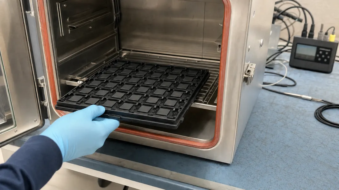
- Remove power and apply the controlled time-temperature exposure.
- Return samples to a defined stabilization temperature before electrical testing.
- Perform one planned readback pass while recording mismatches, latency, retries and exposed health changes.
- Preserve failed addresses and raw diagnostics before rewrite, repair or repeated scans.
The first read can change the state of managed flash. Firmware may invoke read-retry, read-reclaim or refresh. Decide in advance whether the objective is application-visible data survival or characterization of the pre-read margin. The latter normally requires supplier cooperation because standard host interfaces do not expose raw cell distributions or complete ECC information.
Use separate controls to detect chamber, fixture and software errors. An unexposed control confirms that a mismatch was not introduced by the dataset generator. A temperature-logged dummy verifies that the sample experienced the intended profile rather than the chamber set point alone.
Define evidence at three levels
“All files opened” is one result, not the entire retention state.
| Evidence level | Observation | Limitation |
|---|---|---|
| Application | File or record checksum, mount and boot behavior | Internal correction margin is hidden |
| Device | Health, error, retry, latency and lifetime indicators | Vendor exposure varies and counters may be coarse |
| Media/supplier | Raw bit-error distribution, ECC margin, threshold shift and internal refresh | Usually requires proprietary access and product-specific interpretation |
KIOXIA's automotive retention discussion links temperature, wear, WAF and refresh rather than treating retention as an isolated catalog value [3]. A refresh strategy can reduce risk, but it becomes part of the system requirement: the product must be powered often enough, firmware must cover the full relevant address space, and refresh completion must be observable.
Product specifications also use different retention boundaries. For example, Micron's 7600 brief states three months at 40°C power-off at end of life [4]. That is a defined product condition, not evidence for every SSD or every temperature. JEDEC JESD218 provides the endurance framework for SSD classes [5]; procurement should cite the applicable revision and class rather than copying a duration without its assumptions.
Separate qualification from field prediction
Accelerated tests are strongest when used to compare a stated model with observations and weakest when extrapolated far beyond the tested domain. Report:
- the number of devices, lots and capacity/firmware strata;
- wear conditioning and its uncertainty;
- actual sample temperature versus time;
- data volume, pattern and address coverage;
- read procedure and whether it may initiate refresh;
- corrected and uncorrected outcomes available at each evidence level;
- model, parameter source and extrapolation interval;
- deviations, censored samples and laboratory failures.
Large production studies show that field reliability contains effects not fully captured by isolated component experiments [6]. A retention test therefore supports one part of the reliability case. It does not replace monitoring, lot traceability, firmware control or system-level redundancy.
If zero user-data errors are observed, the conclusion is limited to the tested sample and exposure. It does not establish an unlimited retention duration or a zero field-failure probability. Confidence must be discussed separately from pass/fail.
Put retention into the RFQ and approval record
Ask the supplier for a per-part retention statement containing:
- NAND mode and managed-device configuration;
- beginning- and end-of-life conditions;
- operating and unpowered storage temperatures;
- target retention duration and error criterion;
- supported WAF or lifetime-estimation inputs;
- refresh or read-reclaim assumptions;
- relevant health indicators and interpretation;
- change-notification triggers for NAND, controller and firmware;
- supplier support for accelerated-test correlation and failed-sample analysis.
Link the accepted statement to the fixed-BOM boundary and the qualification plan. If the product stores irreplaceable data while unpowered, system-level backup or replication remains necessary; flash retention is not an archival guarantee.
The commercial question is therefore not “How many years does this flash hold data?” It is: At the end of the required write life, under our measured temperature and power profile, what retention is supported by this exact configuration, and what evidence and refresh assumptions support it? Include those inputs when requesting a matched device through the OEM flash-storage sourcing page.
FAQ
Does a ten-year flash-retention statement apply at every temperature and wear state?
Can an OEM convert a 125°C bake directly into years at room temperature?
Is a successful file checksum after bake sufficient evidence?
References
- KIOXIA — Understanding NAND Flash Memory Data Retention, Technical Brief ↩
- KIOXIA — Conducting a Lifetime Reliability Analysis, Technical Brief ↩
- KIOXIA — Why Data Retention Is Becoming More Critical in Automotive Applications ↩
- Micron — 7600 NVMe SSD Product Brief ↩
- JEDEC — JESD218 Solid-State Drive Requirements and Endurance Test Method ↩
- USENIX FAST 2016 — Flash Reliability in Production: The Expected and the Unexpected ↩
We publish measured usable capacity and welcome trial-batch verification — automotive-grade, direct from the source factory.