
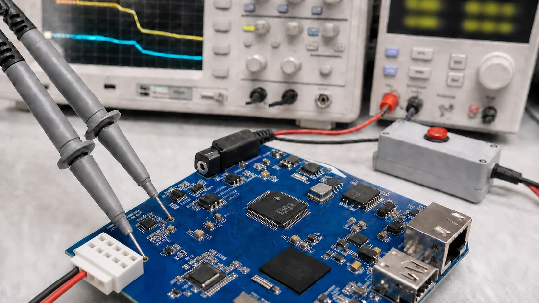
eMMC cache, flush and Reliable Write: power-loss recovery
- A successful application write can still reside in a page cache, filesystem journal, block queue or eMMC write cache; completion must be defined at the required persistence boundary.
- A flush establishes an ordering and persistence boundary only when every layer propagates it correctly and the device implements the promised behavior.
- Reliable Write, cache control and background operations solve different failure modes; their exact scope depends on the eMMC revision, device and configuration.
- Power-loss qualification must use the final board, power tree, software image and exact eMMC part while cutting power at many controlled points and verifying both old and in-flight data.
An embedded controller stores a configuration record, receives a success return and loses power 20 milliseconds later. On the next boot, the record is missing. The immediate accusation is often “bad eMMC,” but the data may never have crossed the persistence boundary the software assumed.
Between an application buffer and NAND cells are several queues, caches and metadata updates. Recovery engineering begins by naming each boundary, then proving that the intended write ordering reaches the exact eMMC configuration used in production.
“Write complete” has several meanings
A simplified path contains at least five stages:
- Application and language runtime. Data may still be buffered in a process or library.
- Filesystem and page cache. The kernel may acknowledge a write before dirty pages or journal records reach the block device.
- Block layer and driver. Requests can be merged, reordered or held before transmission.
- eMMC controller and optional write cache. The managed device may acknowledge data held in volatile cache according to its enabled features and command semantics.
- Flash translation layer and NAND. User data, mapping metadata and error-correction information must be placed into flash consistently.
A normal write() success generally means the bytes were accepted by the operating-system path, not necessarily programmed into nonvolatile media. fsync() or an equivalent call requests a stronger boundary, but the result is only as strong as every downstream layer.
Write the requirement in observable terms. “Configuration committed” might mean that after power removal at any later instant, the system boots, selects either the complete old record or complete new record, and never accepts a torn or checksum-invalid record. That is more testable than “the eMMC must not corrupt.”
Flush and FUA define ordering, not magic
The Linux block documentation separates two important mechanisms. A pre-flush requires writes issued before it to reach nonvolatile storage before later operations proceed. Force Unit Access, represented by REQ_FUA, requires the associated write to complete only after committing to nonvolatile storage [1]. Filesystems and drivers may combine or emulate these operations depending on device support.
This distinction allows a journal or copy-on-write design to order events:
write new data
  -> persist data
  -> write commit marker
  -> persist marker
After interruption, recovery accepts the new state only if the marker and its referenced data are valid. The device cannot infer this application-level transaction by itself.
Disabling filesystem barriers or flushes for a benchmark can invalidate the recovery model. F2FS documentation, for example, describes barrier, nobarrier and flush_merge as explicit controls over write ordering and flush handling [3]. A performance result obtained with weaker persistence settings must not be presented as equivalent to the production configuration.
eMMC cache is a configuration, not an assumption
Managed flash can expose an optional write cache whose status and control are represented in the device's Extended CSD registers. Linux mmc-utils can read and parse EXT_CSD, enable or disable cache where supported, configure background operations and control write reliability per partition [2]. That makes the production register state part of the device specification.
Cache can improve responsiveness and absorb bursts. It can also create a window in which acknowledged data has not reached NAND. The correct decision is not “cache on is unsafe” or “cache off is safe.” Disabling it may increase flush latency or reduce throughput, while host caches, incomplete transactions, FTL updates and weak power rails remain.
Record the exact part number, firmware revision where exposed, eMMC revision, cache size, cache enable state and partition configuration. Read them back from production samples. A golden software image does not guarantee identical behavior if the storage configuration or BOM changes.
Reliable Write addresses a narrower contract
eMMC Reliable Write is intended to improve atomicity or reliability for writes made with the defined reliable-write mechanism. Its supported granularity, eligible partitions and configuration depend on the eMMC revision and device implementation. The relevant capability and settings must be checked through EXT_CSD and the supplier's device documentation.
It should not be expanded into a claim that all data survives every interruption. Three categories must be tested separately:
| Data category | Main question after power loss |
|---|---|
| Previously committed static data | Did unrelated old data remain readable and unchanged? |
| In-flight user data | Is the result complete old data, complete new data or a torn mixture? |
| Device/filesystem metadata | Can mappings, allocation structures and journals recover consistently? |
A reliable update design commonly uses dual records, monotonically increasing sequence numbers, checksums and a final commit marker. Reliable Write may strengthen selected operations, but the software still needs a recoverable data format and explicit ordering.
This is not the same question as SSD hardware PLP
Hardware power-loss protection in an SSD asks whether stored energy and controller firmware can finish defined internal work after input power disappears. This article asks a different question: whether the host application's persistence request reaches an eMMC with the intended ordering and whether the application can recover an interrupted transaction.
The two subjects meet at the system power boundary, but they are not interchangeable. An eMMC design can be recoverable without a supercapacitor when it uses atomic records, verified ordering and arbitrary-interruption recovery. Conversely, a drive with hardware PLP cannot repair an application that writes its commit marker before its payload. For the device-level boundary, see SSD power-loss protection explained.
Background operations and FTL state matter
The eMMC controller performs wear leveling, garbage collection, block retirement, ECC management and mapping updates. Some work occurs in the foreground; supported devices can expose Background Operations status and controls. eMMC BKOPS explains why maintenance can affect latency and why allowing idle maintenance may reduce emergency work later.
A power interruption during internal management is not equivalent to one during an idle read. Qualification must include sustained writes, high fill, deletion and rewrite, BKOPS activity and transitions around flushes. It must also preserve previously written reference regions so the test detects collateral damage outside the file being updated.
Device health is another axis. EXT_CSD life-time estimates and pre-EOL information do not predict the exact failure instant, but they help separate a fresh-sample result from behavior near a defined wear condition. See eMMC health registers for interpretation limits.
Power integrity is part of the storage protocol in practice
Even perfect software ordering cannot compensate for an undefined supply collapse. Measure the eMMC rails at the package or nearest practical test point, not only at the bench supply. Capture voltage, current and reset behavior during normal write, flush and forced interruption.
Define at least:
- nominal voltage and tolerance;
- voltage drop rate and rail sequencing;
- brownout-reset threshold and reset propagation;
- hold-up time from power-fail detection to the eMMC minimum operating voltage;
- whether the processor can issue and complete a final persistence action inside that interval;
- back-power paths through I/O pins or peripherals.
If the product promises graceful shutdown, budget the interval from detection through application quiesce, filesystem sync, device flush and verified power removal. Use worst-case measured latency, not the average. If no hold-up energy exists, design recovery for arbitrary interruption rather than assuming a final flush will run.
A repeatable power-cut test protocol
Use the final PCB, power tree, bootloader, kernel, filesystem, application and exact eMMC part. A development board with a different regulator or driver proves little about the production product.
1. Create identifiable transactions
Write records containing a sequence number, payload length, deterministic payload and checksum. Keep two or more slots so recovery can choose the newest fully valid record. Separately create a static reference region with known hashes.
2. Instrument persistence boundaries
Timestamp application writes, fsync completion, block flush issue/completion and any device-level telemetry available. Capture UART or kernel logs outside the device under test so evidence survives a damaged filesystem.
3. Interrupt at distributed points
Use a programmable switch or supply, not a technician pulling a cable by hand. Cut power before data write, during data write, between data and commit marker, during flush, immediately after reported completion and during background traffic. Combine deterministic offsets with randomized timing to avoid testing one repeatable phase only.
4. Vary the conditions
Cover fresh and preconditioned media, low and high fill, idle and sustained load, cold/room/hot operating points, cache enabled/disabled where the product may use both, and representative fast/slow voltage decay. Choose cycle count from the maximum tolerable failure probability and confidence target, then spread those cycles across the matrix instead of repeating one convenient condition.
5. Classify every recovery
After each reboot, record boot success, mount or filesystem-check result, selected record sequence, checksum state, static-region hashes, kernel errors and time to service. Preserve failed media for analysis instead of automatically reformatting it.
Linux dm-log-writes can record block writes and mark flush/FUA boundaries, enabling replay that simulates failure at many write points [4]. It is valuable for filesystem and software-path development. Hardware power interruption remains necessary because replay does not reproduce regulator collapse or the internal timing of the physical eMMC.
Quantify what zero observed failures means
For n independent Bernoulli trials with zero failures, a one-sided 95% upper confidence bound for the per-trial failure probability is:
p_upper = 1 - 0.05^(1/n)
| Zero-failure cycles | One-sided 95% upper bound |
|---|---|
| 59 | 4.95% |
| 299 | 1.00% |
| 2,995 | 0.10% |
This calculation does not prove that power-cut trials are independent. Repeatedly cutting at one deterministic offset can reproduce nearly the same controller state and overstate coverage. Report both the statistical bound and the distribution across transaction phase, workload, temperature, fill state, wear condition and voltage-decay profile.
Define pass criteria before running the test
A useful release plan separates outcomes:
| Outcome | Example acceptance rule |
|---|---|
| Atomic application update | Recovery returns the complete old or new record; never a torn valid-looking record |
| Previously committed data | All protected reference hashes match after every cycle |
| Filesystem recovery | Boots or completes the approved repair path without manual reformat |
| Availability | Returns to service inside the product deadline |
| Diagnostics | Every detected recovery event is logged outside the affected transaction |
Do not silently group all failures as “corruption.” A missing latest record, an unmountable filesystem, changed old data and a dead device imply different mechanisms and corrective actions.
Procurement and change-control evidence
Request the exact ordering information needed for qualification: part number, capacity, eMMC revision, supported cache and reliable-write capabilities, default and programmed EXT_CSD state, firmware/change policy, operating temperature, endurance scope and any vendor power-interruption guidance. Public technical resources are useful starting points, but the final evidence must match the quoted SKU [5].
Incoming inspection should read identity and configuration registers from samples and retain the values by lot. Mechanical handling also matters: an electrically qualified BGA can be damaged by poor moisture or reflow control, so include storage, baking and reflow records in the flash-storage qualification plan.
For a Kalstor OEM review, provide the schematic power tree, software stack, filesystem and mount options, write transaction, expected interruption profile, temperature range and acceptance rules. The OEM qualification workflow then ties sample identity to the test evidence.
Bottom line
Power-loss recovery is a system property. Application transactions, filesystem ordering, block flushes, driver support, eMMC cache and Reliable Write settings, FTL behavior and the board's voltage collapse all participate. Define the persistence boundary, read back the actual configuration and interrupt the final product at many controlled points. That is how “write succeeded” becomes a claim supported by evidence rather than an assumption.
FAQ
Does fsync guarantee that eMMC data survives a power cut?
Is eMMC Reliable Write the same as power-loss protection?
Should the eMMC write cache always be disabled?
How many power-cut cycles are enough?
References
We publish measured usable capacity and welcome trial-batch verification — automotive-grade, direct from the source factory.