
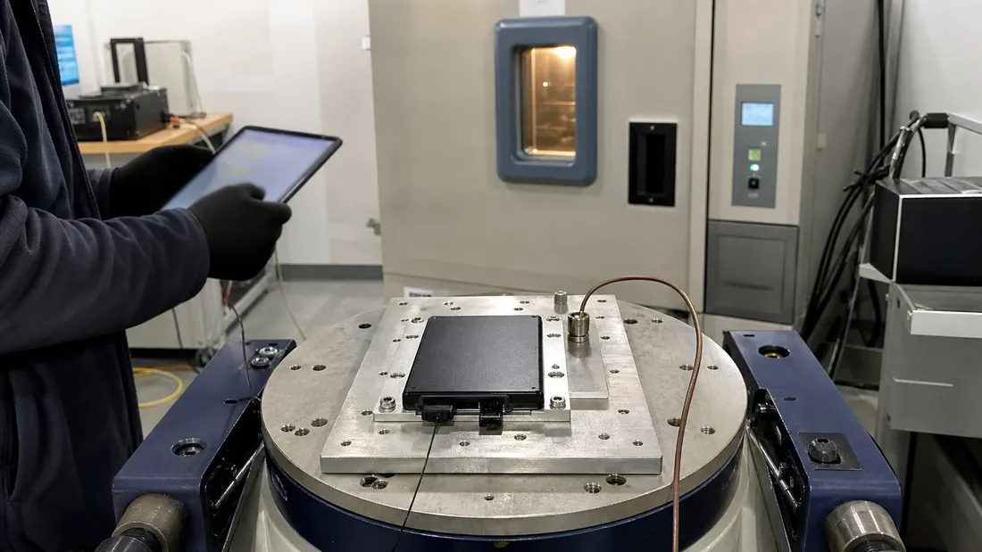
Industrial SSD temperature, vibration and shock testing
- An operating-temperature rating is not an environmental qualification report. The test must define ramp, dwell, cycles, power state, workload and measurements.
- Vibration and shock severity should come from the installed product environment, mounting path and failure consequences—not from copying an unrelated datasheet number.
- Exercise the SSD through the production host while monitoring link errors, latency, data integrity, enumeration and post-exposure diagnostics.
- Qualification applies to the tested SSD BOM, firmware, capacity, fixture and host configuration; material changes require a documented requalification decision.
“Industrial SSD” is a sourcing category, not a complete environmental requirement. Two drives may carry the same temperature-range label while differing in controller, NAND, firmware, package construction, connector retention and the evidence behind the claim.
For an OEM, qualification must connect the field environment, the installed storage assembly and observable system behavior. The goal is not to prove that a bare drive survives an impressive chamber setting. It is to show that the approved SSD and host configuration preserve data and meet the application contract under representative temperature change, vibration and shock.
Translate the field environment into a test basis
Begin with measured or defensible product conditions:
- SSD location, enclosure and heat sources;
- minimum and maximum local temperature, not only external ambient;
- warm-up and cool-down rate during real operation;
- vehicle, rail, machine, fan or transport vibration spectra;
- shocks from handling, installation, doors, drops or machine events;
- orientation, bracket, fasteners, cable mass and connector retention;
- powered, unpowered and transitional operating states;
- workload, fill level, write duty cycle and allowed recovery time.
IEC 60068-2-14 provides standardized change-of-temperature methods [1]. IEC 60068-2-6 addresses sinusoidal vibration and the assessment of mechanical weakness or performance degradation [2]. IEC 60068-2-27 defines shock procedures and emphasizes selecting pulse severity to reproduce operational or transport effects, or to meet an explicit structural requirement [3].
These standards provide methods. The relevant product specification must still select severity, axes, duration, mounting and acceptance criteria.
Freeze the qualified configuration
| Layer | Record before testing |
|---|---|
| SSD | Ordering part number, capacity, serial, hardware revision, controller/NAND boundary and firmware |
| Host | Board revision, BIOS/UEFI, driver, operating system, filesystem and power policy |
| Mechanical path | Production bracket, screws, torque, damping, connector, cable and orientation |
| Thermal path | Enclosure, airflow, heat spreader, thermal pad and sensor location |
| Workload | Block size, queue depth, read/write mix, address distribution, fill level and duration |
| Instrumentation | Chamber probes, accelerometers, shock measurement, power capture and time synchronization |
A test performed on a loose drive connected through a bench adapter may be useful for supplier screening, but it does not automatically qualify the production assembly. If the fixture differs, state the limitation.
Design the temperature-change sequence
Temperature qualification should expose both steady extremes and transitions. Define:
- preconditioning and baseline data set;
- low and high chamber setpoints;
- permitted specimen temperature tolerance;
- transition rate or transfer method;
- dwell criterion based on specimen stabilization, not chamber air alone;
- number of cycles;
- powered state and workload at each segment;
- readback, diagnostic capture and recovery checkpoints.
Place a calibrated sensor near the SSD controller or case location agreed in the plan. Chamber air can reach a setpoint while the controller remains far from it. Conversely, sustained writes may make the controller hotter than the surrounding air.
Use at least two workload states: an application-representative load and a controlled integrity workload with known data. Include cold start, hot start and I/O across transitions if those states occur in the product. Monitor:
- time to enumerate and become I/O-ready;
- data mismatches and unreadable LBAs;
- throughput and latency distribution, including tail latency;
- throttling indicators and temperature telemetry where supported;
- link retraining, resets and operating-system errors;
- new health, media or integrity warnings after each exposure.
The related NVMe thermal-throttling guide explains why a peak benchmark cannot substitute for a time-aligned temperature and latency record.
Design vibration around the installed assembly
Sinusoidal vibration is useful for resonance search and controlled endurance exposure. The plan should state frequency range, sweep rate, displacement or acceleration, crossover where applicable, duration and all tested axes.
Mount the SSD as it will be installed whenever practical. Instrument the fixture and verify that the commanded shaker profile reaches the control point without an unrecognized fixture resonance or notch. Inspect:
- connector intermittency and link resets;
- screw loosening, bracket deformation and cable fretting;
- case or PCB resonance;
- intermittent read/write errors;
- latency excursions synchronized with the vibration profile;
- post-test physical damage and data integrity.
If the product operates during vibration, run the production host and retain a time-synchronized I/O trace. A device that reads correctly after the shaker stops may still be unacceptable if it reset repeatedly during operation.
Random vibration may be more representative for some vehicles and machinery, but it is a different method and should be specified separately. Do not label a sinusoidal sweep as random vibration.
Define the mechanical shock test
Shock testing requires a pulse shape, peak acceleration, duration, direction, pulse count and mounting condition. Select them from the product environment or an applicable customer specification. More severe is not automatically more valid.
IEC 60068-2-27 notes that the specimen is mounted to the shock-machine fixture and that pulse selection should reflect the operational or transport effect where possible [3]. For an SSD assembly, verify the actual pulse at the control point and test relevant positive and negative directions.
Separate three events that are often confused:
| Event | Engineering question |
|---|---|
| Installed operational shock | Does the running system maintain link, data and function? |
| Service or handling shock | Does the removed or serviced assembly remain physically and electrically valid? |
| Packaged transport shock | Does the shipping configuration protect the product? |
They may require different specimens, fixtures and acceptance rules.
Use data integrity as the primary oracle
Before exposure, write a controlled data set whose records contain logical address, sequence number and checksum. Keep the expected manifest on an independent system. During and after exposure, distinguish:
- acknowledged data that must remain correct;
- in-flight writes governed by the interface and cache contract;
- untouched regions that must never change;
- device-level faults versus host, connector or power-path faults.
Capture raw diagnostics before any repair or retry. NVMe health, error and telemetry capabilities can provide evidence around resets and media or data-integrity events [4]. For SATA, retain the applicable device identity, SMART data and host error logs. In either case, a screenshot is secondary to timestamped raw output.
Predefine acceptance and stopping criteria
| Observation | Typical disposition |
|---|---|
| Any mismatch in protected or untouched data | Stop and quarantine |
| Device disappears or changes reported capacity | Functional failure |
| Link reset or error exceeds the product allowance | Interface failure |
| Recovery time exceeds the system budget | Availability failure |
| Permanent deformation, loose connector or fastener | Mechanical failure |
| Tail latency exceeds the agreed envelope | Performance failure |
| New critical health or integrity warning | Stop for failure analysis |
Do not erase the evidence by immediately repeating a failed cycle. Follow the RMA evidence package and preserve the first observed state.
Convert qualification into purchasing control
The release package should contain the environmental basis, exact configuration, sample and lot manifest, calibrated equipment, fixture drawings, temperature and acceleration traces, workload and data oracle, raw diagnostics, results by axis or cycle, deviations and approved conclusion.
Add this RFQ language:
Supplier shall identify the environmental rating and supporting test basis for the proposed SSD, including the covered part number, capacity, firmware and material configuration. OEM approval requires project-specific temperature-change, vibration and shock evidence on the agreed host and mounting path. Controller, NAND, firmware, mechanical or assembly changes are subject to notification and requalification review.
Connect the report to the flash-storage qualification plan and the PCN/EOL change-control process. Qualification remains valid only inside its documented boundary.
Bottom line
Environmental qualification is not a collection of maximum numbers. It is a traceable experiment that applies representative stress to a frozen configuration and observes data integrity, interface stability, latency, recovery and physical condition. That is the evidence an OEM can use to approve an industrial SSD for production.
FAQ
Does an industrial temperature rating prove that an SSD was temperature-cycled?
Can the SSD be tested loose on a vibration shaker?
Should environmental qualification include performance measurements?
References
We publish measured usable capacity and welcome trial-batch verification — automotive-grade, direct from the source factory.