
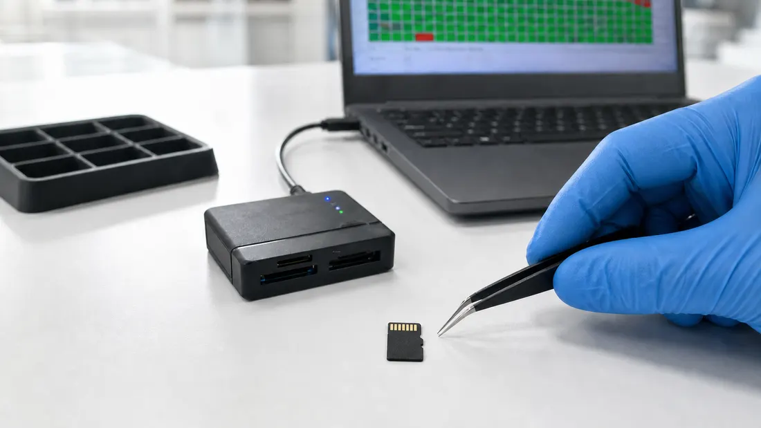
Full-address error scan vs. flash write verification
- A host-visible error scan and a complete write/read comparison answer different questions. Neither result should be reported as if it proves the other.
- A read-oriented scan can expose unreadable logical regions, while full write/read verification tests whether the reported capacity stores and returns newly written data.
- Quick or sampled probes are useful for screening, but the sampling pattern, destructive behavior and untested address space must remain visible in the acceptance record.
- For B2B lots, preserve raw logs, device identity, reader and host configuration, tested byte count, elapsed time and the pre-approved disposition rule.
A green scan map is visually persuasive, but it is not a complete statement about flash quality. A microSD card or USB drive can be readable at the addresses a tool visits and still fail to retain unique data across its claimed capacity. Conversely, a write/read verifier can report mismatched data without identifying the same spatial pattern shown by a block scan.
The distinction matters in procurement. When a report says only “full scan passed,” the buyer cannot tell whether the device was read, overwritten, sampled or compared against known data. The result is difficult to reproduce and weak as a lot-acceptance record.
This article defines three test classes and shows how to combine them without overstating the evidence.
Start with the question, not the software name
| Test class | Main question | Typical operation | Principal limitation |
|---|---|---|---|
| Host-visible error scan | Can the selected logical regions be read without an error? | Read logical blocks and display a spatial map | May not prove that every address retains distinct new data |
| Sampled capacity probe | Do distributed regions behave consistently with the reported size? | Read, write and restore selected regions, or probe selected boundaries | Untested regions remain outside the evidence |
| Complete write/read verification | Does the usable range return the controlled data written to it? | Fill the address space, read it back and compare | Destructive, time-consuming and dependent on the host path |
Tool labels are not test definitions. Record the actual mode, coverage and data operation. The official HD Tune help describes Error Scan as scanning the disk surface and showing defects as red blocks [2]. F3 describes a different operation: f3write fills the mounted device with pseudorandom data and f3read checks whether the same data is returned [1].
These methods can complement each other, but their pass statements are not interchangeable.
What a full-address error scan establishes
A non-quick error scan can traverse the host-visible logical address range and expose regions that return read errors. For incoming inspection, the map is useful because it shows whether failures cluster and gives the operator a reproducible visual artifact.
Record at least:
- device model, reported capacity and available serial or CID data;
- software and version, with Quick Scan or equivalent sampling disabled;
- start and end address, block size if exposed and elapsed time;
- host, operating system, reader, adapter and cable;
- result map, error count and raw export or screenshot;
- sample ID, purchase lot and disposition.
The phrase “bad-block count” should be avoided for this result. Managed flash hides raw NAND, controller spare areas and internal bad-block management from the host. The scan describes host-visible logical access, not the factory NAND defect map.
An all-green map means that the observed reads completed under that configuration. It does not demonstrate that the device can store a new, unique payload at every reported address.
What complete write/read verification adds
Counterfeit-capacity media commonly reports more logical space than the installed NAND can retain. Once writes cross the real capacity, data may wrap, alias earlier addresses or disappear. A format or read-only scan cannot reliably expose that behavior because it may never require every reported address to hold a distinct new value.
F3 provides a transparent model: write pseudorandom content over the mounted capacity, then read and compare it [1]. A defensible procedure should state:
- the device was empty or authorized for destructive testing;
- the verifier wrote across the intended usable range;
- the read phase compared returned bytes with the expected content;
- the tested byte count, corrupted byte count and lost byte count were retained;
- write and read duration were recorded separately;
- any mismatch triggered quarantine before reformatting or retest.
This test answers a stronger capacity-integrity question, but it remains a system result. A weak card reader, unstable USB port, thermal throttling or host sleep event can cause a failure. Preserve the host path so failed units can be retested under a controlled escalation procedure rather than casually rerun until they pass.
Where sampled probes fit
Sampling can reduce inspection time. GRC documents that ValiDrive tests 576 evenly distributed regions by reading original data, writing random noise, verifying it and restoring the original [3]. F3 also offers f3probe, a destructive block-device test that writes only what is necessary for a faster capacity assessment [1].
Those approaches are useful screens, especially for large lots, but the report must preserve the sampling boundary.
| Report wording | Evidence quality |
|---|---|
| “Capacity verified” | Too broad if only a sample or read scan was run |
| “576 distributed regions passed the documented spot check” | Reproducible sampled statement |
| “Usable range was filled, read back and compared with zero mismatched bytes” | Complete write/read statement |
| “Full host-visible read scan completed with zero unreadable regions” | Complete read-scan statement |
Precise wording prevents a fast screen from becoming an unsupported supplier claim.
Build a two-stage B2B acceptance flow
Use risk to decide where time is spent.
| Lot condition | Recommended evidence |
|---|---|
| Established supplier, unchanged part and low-consequence use | Identity check plus documented sample screen |
| New supplier, capacity or controller revision | Larger sample, complete write/read verification and full error scan |
| Private-label retail or device bundle | Complete verification on the agreed sample plus target-host functional test |
| Suspicious capacity, mixed labels or any mismatch | Quarantine; expand to 100% testing or reject pending supplier analysis |
| High-consequence recording or field service cost | Qualification on multiple units and ongoing lot monitoring |
The SD Association defines different capacity families and filesystem mappings [4], but correct SDHC or SDXC identification does not prove physical capacity. Combine the identity checks in the microSD incoming inspection checklist with the evidence hierarchy above.
Preserve failures before they disappear
Do not format, repair or repeatedly scan a failed sample before collecting evidence. Save:
- the first failure map and raw comparison log;
- exact sample and lot identity;
- operating-system event logs where relevant;
- reader, adapter, port and cable identity;
- ambient or device temperature if heat may be involved;
- a checksum of each exported log;
- the decision to confirm, escalate or reject.
If the failure reproduces on a controlled reference reader, move the sample into the flash-storage RMA evidence process. If it does not reproduce, investigate the original host path rather than deleting the first result.
RFQ and purchase-order wording
Incoming samples may undergo destructive full-range write/read comparison and a separate full host-visible error scan. Supplier acceptance evidence must identify the tested range, test mode, software version, host path and error criteria. A sampled or read-only result must not be represented as complete capacity verification.
For a supply program, attach this wording to the broader OEM flash-storage qualification plan and define the sample escalation rule before the shipment arrives.
Bottom line
A block map, a sampled probe and a full write/read comparison are three different pieces of evidence. The reliable B2B workflow is to name each test accurately, preserve its coverage boundary and combine results according to lot risk. That produces a defensible release decision instead of a screenshot that merely looks reassuring.
FAQ
Can a full error scan prove that a microSD card has genuine capacity?
Is a quick scan acceptable for incoming inspection?
Should an error scan run before or after write verification?
References
We publish measured usable capacity and welcome trial-batch verification — automotive-grade, direct from the source factory.