
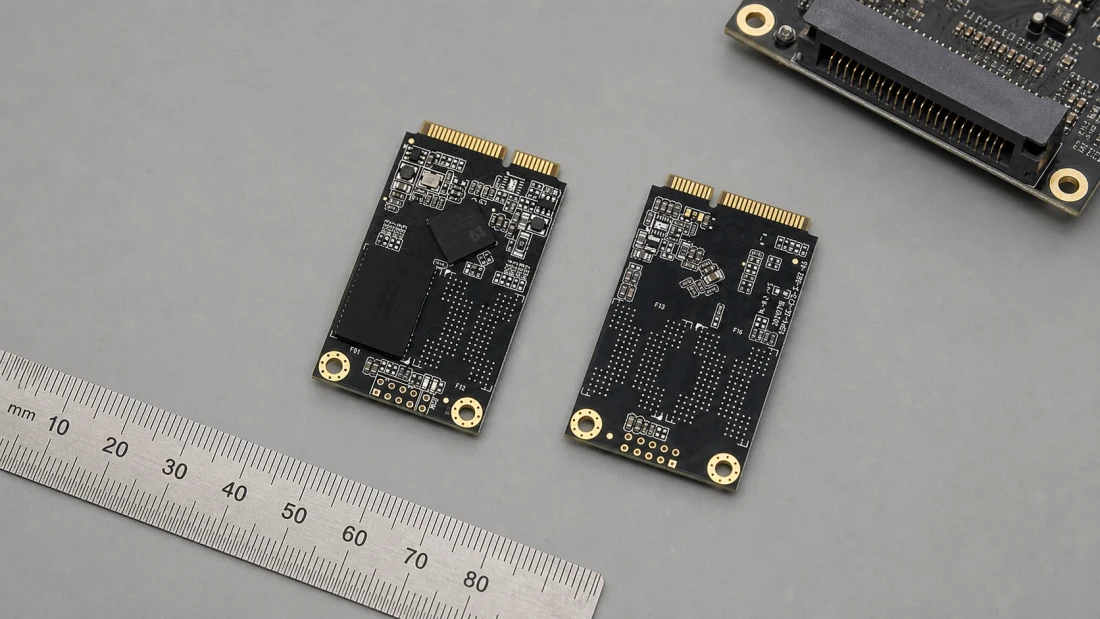
Kalstor mSATA SSD guide: socket, power and host qualification
- mSATA uses SATA signaling through a Mini Card-style connector; physical insertion alone does not prove that a socket routes SATA rather than PCIe or USB.
- The current Kalstor mSATA program publishes a 50.8 x 29.85 x 4.0mm module, 128GB-2TB range, 3.3V input and catalog sequential performance up to 550/500MB/s.
- The SATA 6Gb/s interface label is a link capability, not a guarantee of sustained application throughput or tail latency.
- Approval should bind the exact sample identity, firmware, host, workload and accepted configuration to repeat-order checks.
An mSATA module can slide into a socket that looks correct and still be electrically incompatible. The reason is simple: mSATA reuses a Mini Card-style physical connector, but it carries SATA signals. A socket wired only for PCI Express or USB will not become a SATA host because the card fits.
For a legacy industrial computer, kiosk, vehicle terminal or embedded controller, mSATA can remain a practical storage format. The integration decision has four separate gates: host routing, 3.3V power, mechanical clearance and workload qualification. Skipping any one of them turns a recognizable form factor into an avoidable field failure.
The current Kalstor mSATA product boundary
Kalstor's current neutral portfolio baseline publishes the following family-level fields:
| Field | Published mSATA value |
|---|---|
| Module dimensions | 50.8 x 29.85 x 4.0mm |
| Capacity range | 128GB-2TB |
| Interface | SATA III, 6Gb/s |
| Input voltage | 3.3V DC |
| Sequential read/write | Up to 550/500MB/s |
| Random read/write | Up to 80K/75K IOPS |
| Common NAND field | 3D TLC |
| Common operating/storage range | 0 to 70C / -25 to 85C |
These are portfolio fields, not a universal datasheet for every capacity. “Up to” is a ceiling measured under a particular test setup. The quotation must identify the proposed capacity and part number, and the approval package must state firmware, configuration-control scope, environmental grade and any performance acceptance limits.
Kalstor does not infer current stock, fixed NAND, fixed controller or a permanent lead time from this table. Those are quote-specific facts and need a validity date.
mSATA, Mini PCIe and M.2 are three different checks
SATA-IO introduced mSATA as a small-form-factor SATA interface and defined its connector signals separately [1][2]. The practical result is a three-part identification problem:
| Label encountered | What it describes | What still must be verified |
|---|---|---|
| Mini PCIe / Mini Card | Physical connector family and commonly PCIe/USB routing | Whether the socket also supports mSATA signaling |
| mSATA | SATA protocol on the mSATA pin assignment | Host BIOS/controller support and full-size card clearance |
| M.2 SATA | SATA protocol on an M.2 card and keyed M.2 socket | Card length, key, socket mode and mounting position |
An adapter cannot create a SATA controller where none exists. Some host designs provide a combo socket and select between PCIe and mSATA, but that is a motherboard feature, not a property of the connector shell. Confirm the board manual, schematic or vendor support statement. A label such as “WWAN” or “Mini PCIe” is not sufficient evidence.
Before ordering samples, capture:
- motherboard and BIOS revision;
- socket designation and routed interface;
- whether the socket accepts a full-size 50.8mm card;
- mounting-point location and screw hardware;
- maximum component height on both card faces;
- 3.3V rail tolerance and available current;
- boot support if the SSD will contain the operating system.
Mechanical fit is more than width and length
The Kalstor module baseline is 50.8 x 29.85 x 4.0mm. The host still needs enough room for the socket, insertion angle, retaining screw and components on the populated side. Nearby shielding, a battery, a fan duct or the enclosure wall can collide even when the PCB outline fits.
Inspect the stack in the final enclosure. Record the socket-to-standoff distance, card-side orientation and keep-out volume. Check that the retaining screw clamps the card without bending it and that service technicians can remove it without levering against nearby components.
For vibration-prone equipment, the connector and retaining method belong in the mechanical qualification. A storage benchmark on an open bench does not reveal intermittent contact caused by chassis vibration or an unsupported card edge.
Power integrity starts at the 3.3V socket pins
The published Kalstor mSATA family uses a 3.3V input. The relevant voltage is the waveform at the socket during startup, sustained writes and shutdown, not only the nominal regulator label.
Measure at least:
- minimum voltage during inrush and host startup;
- steady-state ripple during sustained write;
- rail collapse and reset behavior during abrupt removal;
- sequencing relative to the host controller and reset signals;
- behavior across the product's input-voltage and temperature corners.
A marginal rail may present as enumeration delay, link reset, filesystem damage or an apparently dead SSD. Those symptoms should not be assigned to NAND before the power waveform and host log are captured.
Do not generalize a power-loss-protection claim from another form factor. The current Kalstor portfolio baseline identifies hardware PLP for a 2.5-inch SATA family; it does not establish the same feature for the mSATA family. Any mSATA PLP behavior must be confirmed on the quoted SKU and tested with the final host.
Interpret 6Gb/s and 550MB/s correctly
“SATA III 6Gb/s” describes the interface generation. “Up to 550MB/s read and 500MB/s write” is a product-family performance field. Neither predicts every application workload.
Observed throughput and latency depend on:
- host SATA controller and driver;
- transfer size and read/write ratio;
- command concurrency and NCQ behavior;
- compressibility and data pattern used by the tool;
- free space, fill level and prior write history;
- SLC-write-cache state and background garbage collection;
- temperature and controller throttling;
- capacity and exact firmware/configuration.
A short sequential run on an empty sample mainly answers whether the path can move large contiguous transfers quickly. It does not answer whether a logging application maintains its required rate after hours of overwrite, or whether database sync latency remains inside a deadline.
Define an application floor instead. For example: “while the device is 80% logically filled, sustain the production 70/30 read/write trace for eight hours at the required temperature; report bandwidth and p50, p95, p99 and maximum command latency.” The numbers in that sentence must come from the product requirement, not from this example.
A host-qualification sequence
1. Freeze the test object
Record the mSATA label, capacity, serial number, firmware, reported identity and sample trace code. Record the host board, BIOS, operating system, storage driver, test-tool version and power configuration. Without both identities, a pass cannot be reproduced.
2. Prove enumeration and boot behavior
Run cold starts, warm restarts, suspend/resume and approved recovery modes. If the product boots from mSATA, test firmware update, watchdog reset and failed-boot recovery. Keep host logs for every failure rather than counting only successful boots.
3. Verify the reported address range
Use a destructive full-address write/read verification on dedicated samples before placing valuable data on them. Store the data pattern, tool version, duration and mismatch count. A read-only scan cannot prove that every address accepts newly written data.
4. Run the production workload
Precondition the drive to the intended fill and write state, then replay the actual or representative I/O trace. Report sustained throughput and latency percentiles over time. Keep temperature and SMART/ATA health output where the exact device exposes useful attributes; attribute meanings can be vendor-specific.
5. Exercise power transitions
Separate clean shutdown from abrupt interruption. Define which data may be lost, which previously committed data must remain unchanged and what recovery time is acceptable. A successful reboot alone is not proof that in-flight and old data are correct.
6. Inspect the final mechanics
Test the closed enclosure under the required temperature, vibration and shock conditions. After exposure, repeat enumeration, identity and checksum checks. This links mechanical survival to storage behavior instead of treating them as unrelated reports.
From approved sample to repeat order
The approval record should state which fields are fixed and which substitutions require review. A useful mSATA boundary includes:
| Control field | Approval question |
|---|---|
| Commercial part number | Is the repeat order the same approved item? |
| Capacity and user-visible geometry | Does the host and image layout still match? |
| Firmware | Is the version identical or inside an approved branch? |
| Controller/NAND scope | Is it fixed, equivalence-controlled or unspecified? |
| Performance acceptance | Does the incoming sample pass the same workload and limits? |
| Temperature grade | Does the quoted range match the application? |
| Change notification | Which changes trigger document review or requalification? |
“Same mSATA, same capacity” is not a complete equivalence rule. A substitution can preserve the connector and peak benchmark while changing latency, power behavior, endurance, firmware or host compatibility.
What to send Kalstor for an mSATA review
Send the host board and BIOS revision, socket routing evidence, required capacity, operating system, workload trace or numerical duty cycle, temperature range, power-interruption profile, mechanical constraints, forecast and fields that must remain controlled. Kalstor can then separate the published family range from the configuration that is actually being quoted.
For a broader interface comparison, see the Kalstor SATA-versus-NVMe selection guide. For acceptance evidence, use the flash-storage qualification plan.
Bottom line
mSATA is not “whatever fits a Mini PCIe-looking socket.” It is a SATA storage interface with a specific pin assignment, mechanical envelope and host dependency. Verify the routed interface, 3.3V rail and clearance first; then qualify the exact Kalstor sample with the final host and workload. That sequence turns a legacy connector choice into a controlled storage design.
FAQ
Can an mSATA SSD be installed in any Mini PCIe socket?
Is mSATA the same as M.2 SATA?
What are the published Kalstor mSATA specifications?
Does 550MB/s mean the drive will sustain 550MB/s in my product?
References
We publish measured usable capacity and welcome trial-batch verification — automotive-grade, direct from the source factory.